This wiki article covers the KY-050 / HC-SR04 ultrasonic sensor. Included are wiring diagrams, code examples, pinouts, and technical data. This sensor contains an ultrasonic emitter and receiver that combined together can be used to determine its distance from an object by measuring the time it takes sound to travel from the emitter and its return to the receiver.

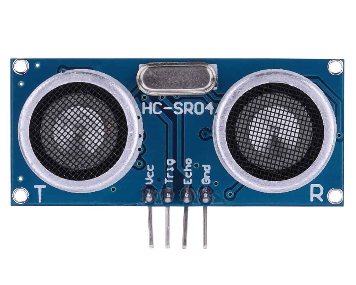
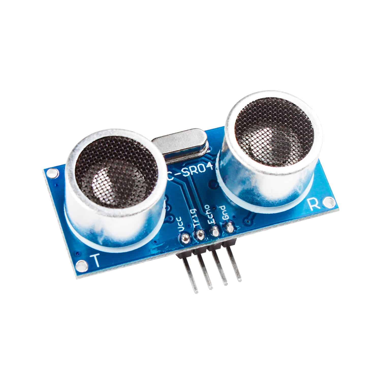
The KY-050 / HC-SR04 ultrasonic sensor has four pins: Vcc+, Trigger, Echo, and Ground
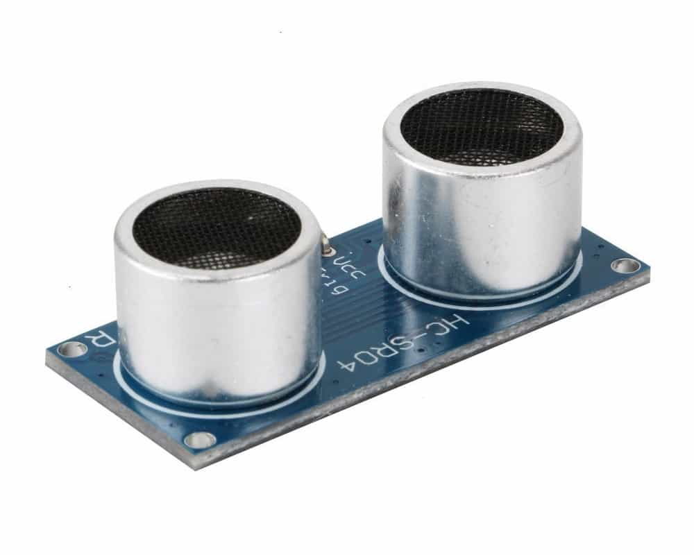
The ultrasonic sensor contains both and emitter and a transmitter that operate that the 40kHz frequency. This frequency is outside of the ability of humans and most animals hearing ranges.
Tech Specs for the KY-050 / HC-SR04 Ultrasonic Sensor:
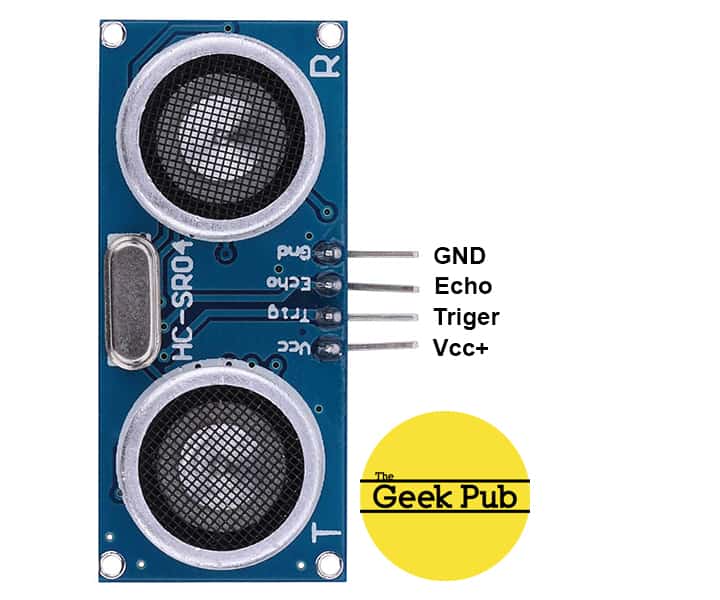
This module has three pins: Vcc+, Trigger, Echo, and Ground
The KY-050 / HC-SR04 ultrasonic sensor pinout is as follows:
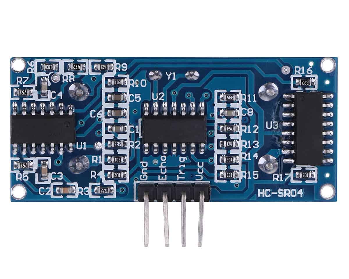
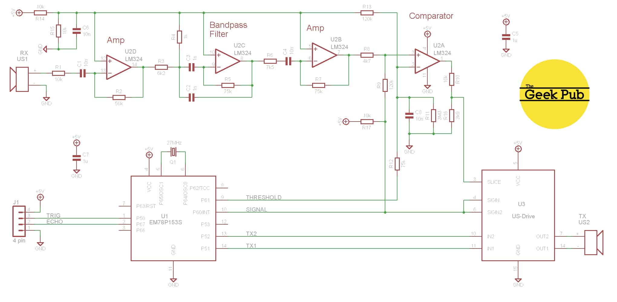
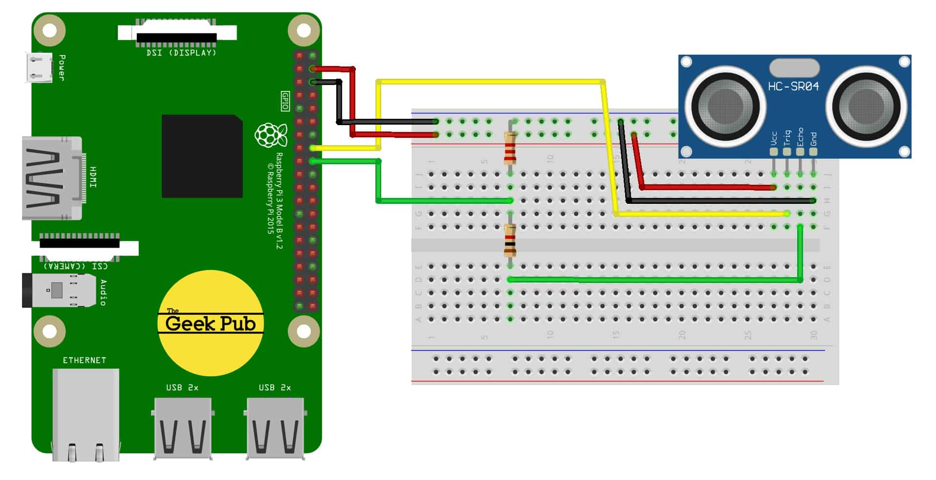
The KY-050 / HC-SR04 ultrasonic sensor schematics is as follows:
The following Geek Pub projects use the KY-050 / HC-SR04 ultrasonic sensor module:
You’ll find below code examples of using the KY-050 / HC-SR04 ultrasonic sensor module with both the Arduino and the Raspberry Pi (Python).
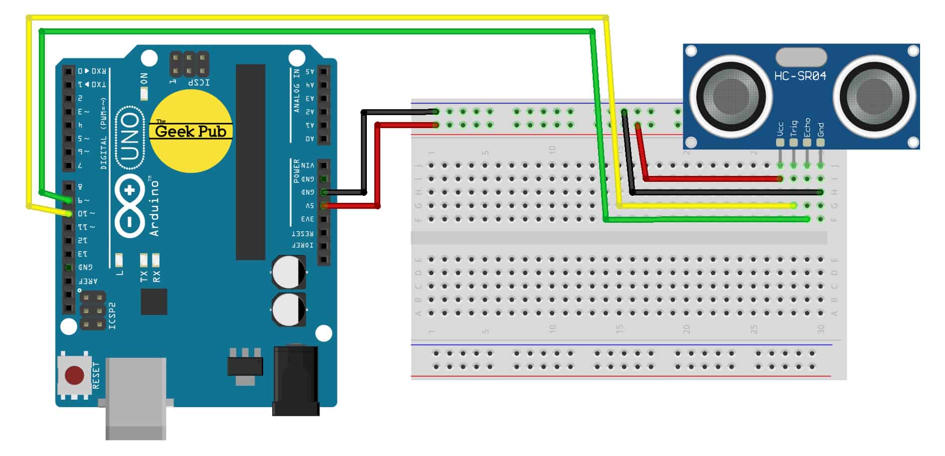
The following code example is for the Arduino. This code will pulse the ultrasonic sensor and display the output in centimeters on the serial console.
// Arduino Ultrasonic Sensor Tutorial
// ©2019 The Geek Pub. Freely distributable with attribution

// Defines the sensor pins
const int echoPin = 9;
const int triggerPin = 10;

// defines variables
long timetofly;
int distance;

void setup() {
  pinMode(triggerPin, OUTPUT); // Sets trigger to Output
  pinMode(echoPin, INPUT); // Set echo to Input
  Serial.begin(9600); // Starts the serial communication
}

void loop() {

  // Clears the triggerPin
  digitalWrite(triggerPin, LOW);
  delayMicroseconds(2);

  // Sets the triggerPin on HIGH state for 10 micro seconds
  digitalWrite(triggerPin, HIGH);
  delayMicroseconds(10);
  digitalWrite(triggerPin, LOW);

  // Reads the echoPin, returns the travel time in microseconds
  timetofly= pulseIn(echoPin, HIGH);

  // Calculating the distance (Time to Fly Calculation)
  distance= timetofly*0.034/2;

  // Prints the distance on the Serial Monitor in CM
  Serial.print("Distance: ");
  Serial.println(distance);
}The following code example is for the Raspberry Pi using the Python programming language. This code will pulse the ultrasonic emitter and read the ultrasonic receiver. It will output the distance on the terminal window in centimeters.
*** It is important to use both a 1K ohm and a 2.2K ohm voltage divider to protect the Raspberry Pi pins from damage.
import time
import RPi.GPIO as GPIO
GPIO.setmode(GPIO.BCM)

# Pin to use on GPIO header
TriggerPIN = 33
EchoPIN = 32

# setup GPIO
GPIO.setup(TriggerPIN, GPIO.OUT)
GPIO.setup(EchoPIN, GPIO.IN)
GPIO.output(TriggerPIN, False)

# Main loop

while True:
# Distance measurement will be started with a 10us long trigger signal
GPIO.output(TriggerPIN, True)
time.sleep(0.1)
GPIO.output(TriggerPIN, False)

# The stop watch will start here
Timer1 = time.time()
while GPIO.input(EchoPIN) == 0:
Timer1 = time.time() # The time will be saved till the signal is active

while GPIO.input(EchoPIN) == 1:
Timer2 = time.time() # The last time will be recorded in which the signal was active

# The difference between the times gives the searched duration
Duration = Timer2 - Timer1
# With it you can calculate the distance
Distance = (Duration * 34300) / 2

# The value of the distance will be reduced to 2 numbers behind the comma
Distance = format((Duration * 34300) / 2, '.2f')
# The calculated distance will be shown at the terminal
print("Distance:"), Distance,("cm")

# Sleep half a second before the next check.
time.sleep(.5)
We hope this wiki article has been helpful to you. Please leave a comment below if you have any questions or comments, as we try to keep these articles constantly up to date.