Arcade Controls Wiring Instructions
This page covers the arcade controls wiring instruction for The Geek Pub arcade kits. This includes wiring diagrams for the joystick, buttons, LEDs, and zero-delay encoder boards. If you do not have a Geek Pub arcade controls kit, these instructions may still be useful, as most arcade kits are fairly standard wiring.
These instructions may also be useful for adapting arcade controls and buttons to other platforms, such as Arduinos or Raspberry Pi computers.
Wiring the Arcade Buttons
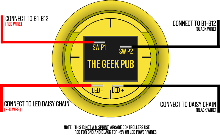
The first step in our Arcade Controls wiring, is understanding the buttons. The buttons have four pins on the bottom that are separated into two pairs: The microswitch and the LED.
Wiring the Arcade Button Microswitch
The microswitch are the two pins that inset in a gray or black plastic housing. This pins are switched by pressing the arcade buttons. These will go to the B1-B13 connections on the arcade controls zero-delay encoder board., Polarity isn’t technically important, but we recommend keeping the red wire on pin 1 and the black wire on pin 2 for simplicity sake and later troubleshooting.
Wiring the Arcade Button LED
The LED pins are the pins placed directly below the microswitch housing. The pin on the left is the LED cathode (or negative wire [-]). The pin on the right is the LED anode (or positive wire [+]).
NOTE: Arcade controls for decades have wired the red wire to the negative and the black wire to the positive. We don’t know why this was decided, but it is backwards from standard convention. The black wire from the encoder board indeed delivers +5V and the red is indeed ground.
It is possible to reverse the polarity by rewiring the header on the LED pins should you choose to change this.
ATTENTION: We have had a small amount of the smaller 24mm buttons come with the positive and negative leads reversed. If your smaller 24mm buttons are not lighting up, please try swapping the red and black LED wires on the back of the button.
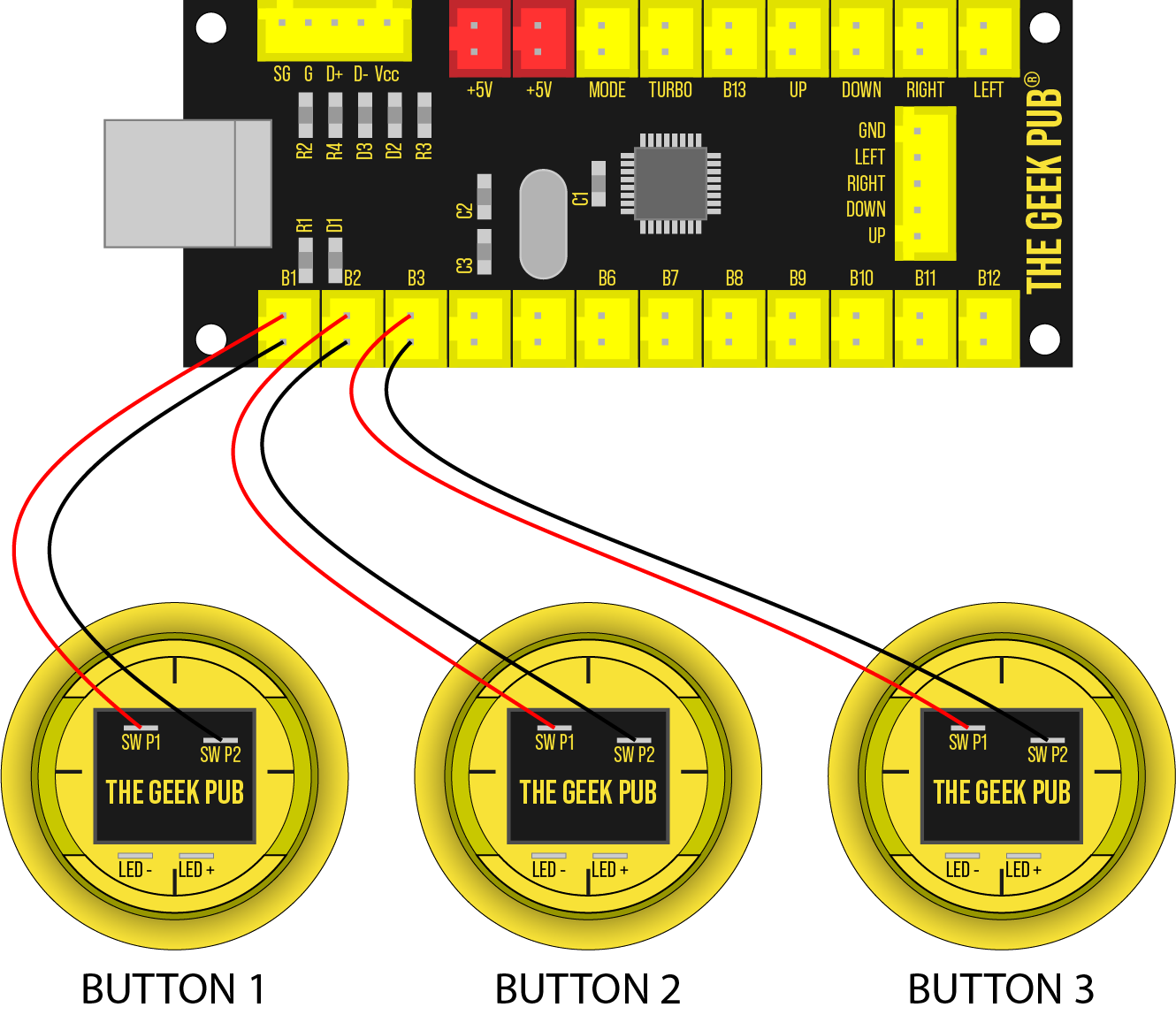
Arcade Controls Wiring: Button Diagram

Arcade Controls Wiring: Connecting to the Encoder
The arcade controls wiring wouldn’t be complete without connecting everything to the encoder board. In this section, we will cover the basics of this board, its pinout, and wiring diagrams.
The zero-delay encoder does have some basic protection for miswiring. However, we highly recommend you check each wire before supplying power to the board as it is possible to damage the board if wired incorrectly.
Zero-Delay Encoder Board Pinout
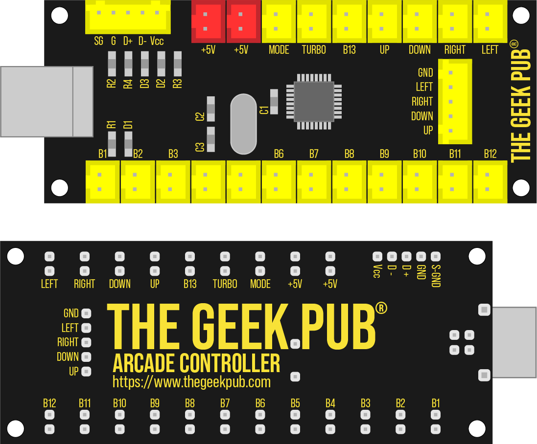
The zero-delay encoder is a fantastic piece of equipment. It has all of the connections needed for a single player set of controls. You’ll need two zero-delay encoder boards to connect a 2-player kit. Both encoder boards will connect via USB to your PC or Raspberry Pi. The encoder board is also powered from this USB connection.
Connections
This section covers the pinout of the zero-delay encoder board.
- USB: There are two USB connections The first one is the a standard USB type B port. The second is a header style USB port (top left header). Use either, but not both at the same time.
- 5V: There are two +5V headers for powering the button LEDs
- MODE: This header is for connecting a button to toggle between Analog and Digital joysticks. Our builds only use the digital mode, so this should not be connected.
- TURBO: If you connect a button to turbo, you can use this button to “repeatedly press fire.” To do this hold the button you want to repeat (B1-B13) and while held press the TURBO button. The B1-B13 button held down will now act as if it is being repeatedly pressed.
- UP/DOWN/LEFT/RIGHT: These two pin ports allow you to hook up a button for movement instead of a joystick.
- JOY HEADER: The 5 pin header for connecting your digital joystick.
- B1-B13: Connections for your individual buttons.

Button Wiring
The microswitches on the buttons each connect to the B1-B12. For simplicity we recommend connecting them in the correct order (i.e. Button 1 to B1, Button 2 to B2). However, it technically doesn’t matter as you will have the opportunity to map each button during the RetroPie setup.

LED Button Daisy Chain
This is where the arcade controls wiring is little unique. The wires that go to the LED’s are a long string of daisy chained terminals. You will connect the plug to one of the red +5V headers on the encoder and then daisy chain each button as shown. If you skipped to this part, please see our note above about polarity. The +5V is on the black wire, and ground is the red wire!
NOTE: Due to supply chain shortages during the pandemic, the board you receive in your arcade kit may have a slightly different layout and be green in color. Although some sockets are in a different orientation, the wiring is otherwise the same.
ATTENTION: Shorts and Damage by Miswiring
It is important to understand that these are electronic components. Failure to wire them properly will cause damage to them. The most common mistake new builders make is reversing the LED and switch wires. This will immediately ground your board’s encoder chip directly to the 5V line and damage that input.
When installing these kits do not allow the boards to touch anything metal while powered on. Do not allow loose wires or button contacts to touch the board. This will cause damage and it is not covered!
WE DO NOT COVER COMPONENTS OR BOARDS THAT HAVE BEEN DAMAGED DUE TO SHORTS OR MISIWING INDICATED BY DAMAGED BOARD TRACES OR BLOWN SHUNTS.
If you damage a single button input, you should be able to simply not use that connection and use one of the two extra inputs (B11-B12). That is, if you damage B1, use B2-B11 for your buttons instead of B1-B10. Retropie does not care which button is connected to which input.
If you have damaged a component and need a replacement part you can order them here:
Arcade Controls Wiring FAQ & Troubleshooting
The following FAQ answers some common questions about wiring your arcade controls.
Q: Can I power the LED’s separately from the Zero-Delay encoder?
A: Yes. You can supply the LEDs power from any 5V power source. However, you will need to add an inline resistor. In most cases a 220 to 330 Ohm resistor should be fine. Failure to add an inline resistor will cause the LEDs to burn out in short order! The zero-delay encoder has an integrated resistor for this reason.
Q: Can I use two 2-player kits to make a 4-player arcade cabinet?
A: Absolutely. However, You may need to add a powered USB hub to your Raspberry PI for the additional two controllers as the Raspberry Pi likely doesn’t have enough current for all of those extra LEDs. Or you may consider powering the LEDs separate from the zero-delay encoder using an external power supply and current limiting resistor.
Q: My boards turn off and the Pi stops recognizing them after only a few seconds.
A: This is almost always due to overloading the Pi’s USB ports. The Raspberry Pi’s USB ports are limited to a maximum of only 1200ma regardless of which power supply you use. However, if you have HATs or other things consuming power it can be far less than 1200ma! It takes very little plugged into the Pi’s ports to exceed its ratings. We highly recommend a powered USB hub rather than powering the boards+LEDs+speakers all from the Pi. Speakers alone can exceed the Pi’s maximum power output.
Q: After booting my PC, I have to unplug and plug the controllers back in to get them to recognize.
A: Sounds like you are using a Dell PC. Many Dell BIOS revisions do not properly hand over HID devices correctly to the operating system. On some Dell PCs you can upgrade/downgrade your BIOS. On other PCs there is no fix. This mostly effects older Dell computers, but even some newer units are effected. This issue is not unique to Geek Pub controllers as all HID devices are affected. We cannot provide support on this issue. We recommend contacting Dell.
Q: My boards are recognized by Retropie/Windows/etc, but none of them do anything.
A: This is almost definitely a short or miswire. The boards have some basic short protection. We recommend you start by connecting only one joystick and one button to a single controller without the LEDs connected. Then you can reconnect each button until they stop working. When that happens you have identified the miswired button.
The most common mistake is connecting the encoder to the LED pins rather than the switch pins on the buttons.
Q: How do I disconnect a button once it is connected? It seems stuck!
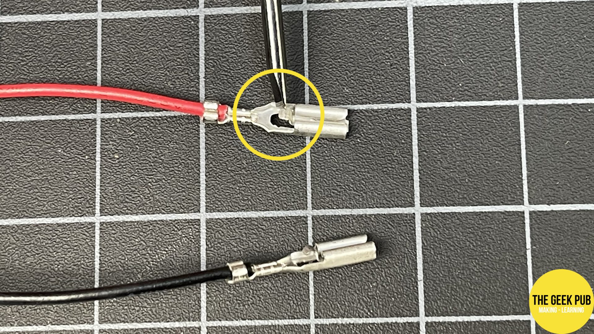
A: The wiring uses locking push-on connectors. These are have a small lever/button that must be pressed to release them. The button is located at the top of the connector on the inner side. We cannot replace wires that were pulled out of the connector improperly.

Q: I burned out a button/LED/joystick/encoder board by miswiring it. Will you replace it?
A: Replacement parts are available here: Individual Buttons. Joysticks, Knobs, Encoder Boards. We cannot replace damaged parts for free.
Shop Geek Pub Arcade Joystick and Button Kits
If you don’t already have a Geek Pub kit, take a second to look over our high quality arcade controller kits!
