Blog
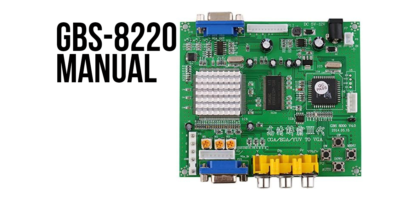
GBS-8200 Manual (CGA to VGA converter)

This GBS-8200 manual covers the configuration, operation, and troubleshooting for the GBS-8200/GBS-8220. It converts CGA, EGA, and YUV (component) to VGA. This allows you to connect older equipment to VGA TFT monitors or to new HDTVs that have a VGA input.
You can buy the GBS-8200 in our online store.
GBS-8200 Features
- Supports CGA, EGA, and YUV (component) signal input
- Supports VGA at
- 640×480
- 800×600
- 1024x768
- 1360×768
- CGA and EGA signal auto scan at 15, 24,, and 31 KHz
- YUV (YPbPr) signal auto scan at 480i/480p, 576i/576p, 720i/720p, and 1080i/1080p
- On-screen display supports English and Chinese
- Adjustable position zoom controls
- True digital 24-bit A/D converter for true 16.7-million color conversion
- Supports all VGA monitors, including CRT, LCD, PDP, and projectors
PACKAGE CONTENTS
In addition to this GBS-8200 manual, the following items are included in the box:
- The main GBS-8200/GBS-8220 PCB
- Power Cable (2 pin, +5V)
- TGB Cable (8 pin, 6 wire)

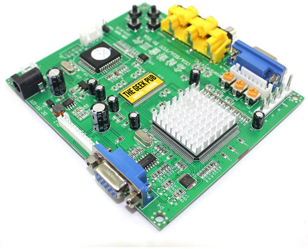
GBS-8200 CGA/EGA to VGA Converter
This is the latest revision GBS-8200 CGA/EGA/YUV (component) to VGA converter for arcade machines.
GBS-8200 Menu Control
| MENU ITEM | DESCRIPTION |
|---|---|
| MENU | Opens the on-screen-display (OSD) and works as the “enter” key. |
| UP | up / increase |
| DOWN/AUTO | down / reduce When not in the OSD menu: Press this key to auto scan for a CGA or EGA signal. Press and hold for 5 seconds, then release to reset the system. |
| SW | When not in the OSD menu: Switches input signal between YUV / RGBS / RGBHV. |
| Clamp sp / Clamp st | This is for adjusting the output if your picture has black spots or discolorations. |
Power Supplies
- Power cable (2 Pin Connector)
- Multi-Voltage Power Supply:
- Switching Power Supply (Center Positive)
- Input: 100-240VAC
- Output: 5V DC 2.0A
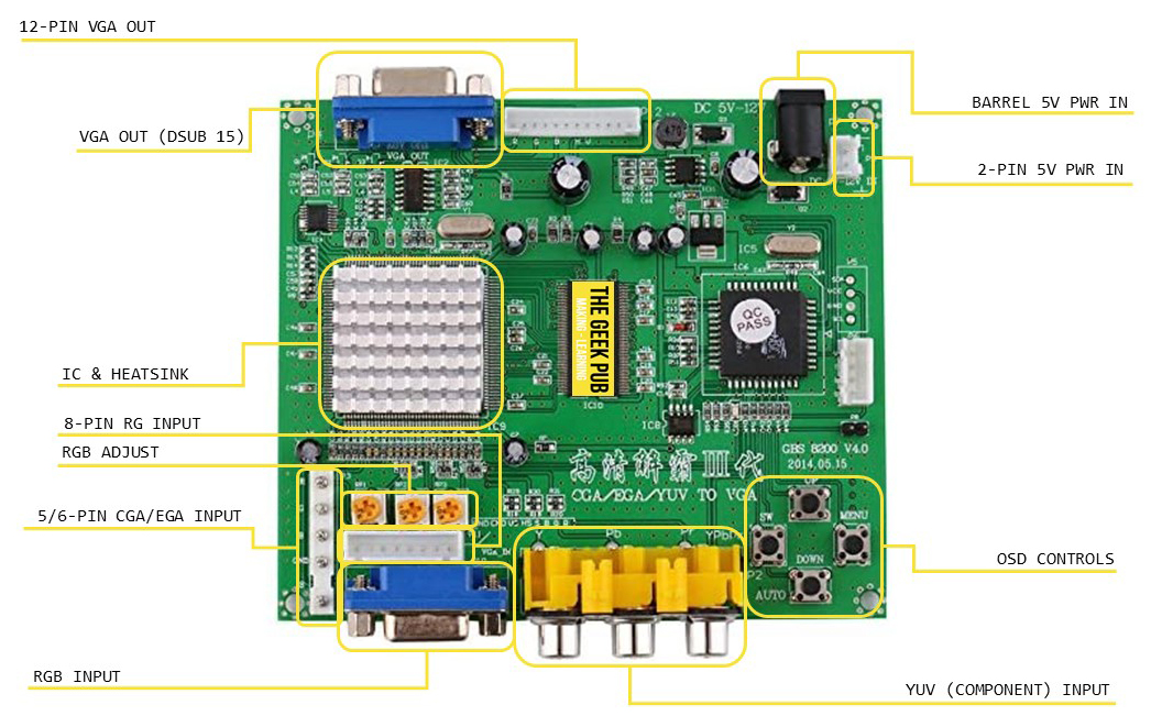
GBS-8220 Board Layout and Diagram
No GBS-8200 manual would be complete without a board layout and diagram! The board is laid out as follows:

GBS-8220 Manual: Basic Configuration and Installation
Connect the output monitor (your VGA monitor) to:
- The VGA OUT connector (sometimes labeled P4), if your monitor uses a 15-pin DSUB connector.
- To the 12 pin VGA header if your monitor has a ribbon cable.
Connect the CGA, EGA, or YUV output from your JAMMA connection to:
- The 5 pin RGB input header if your JAMMA connector already has one wired up (most common).
- Or, use the included 5 pin RGB adapter cable and make the following connections:
- Red Video to Red Wire/P11 (R)
- Green Video to Green Wire/P11 (G)
- Blue Video to Blue Wire/P11 (B)
- H. Sync to Gray Wire/P11 (S)
- V. Sync to Yellow Wire/P11 (VS)
- Ground Ref to Black Wire/P11 (GND)
For more information on the JAMMA Pinout go here.
Connect the GBS-8220 PCB to your +5VDC Power Source:
- Connect the RED wire of the power cable to the +5VDC source and the BLACK wire to the DC GROUND source. connect the 2-pin.
- Connector the power cable to P9 on the GBS-8220 converter PCB.
Note: The power requirement for the GBS-8220 is +5VDC +/- .5VDC @ 2A. If the power supply is unable deliver 2amps, the GBS-8200 will behave erratically.
Power up the GBS-8220 Converter
- Power up the GBS-8220 converter and wait 5 seconds.
- Press the AUTO button on the GBS-8200/8220 PCB. This should self-adjust and lock-in the picture on your VGA output monitor.
If you don not see a picture:
- Remove the P11 wire harness from the converter P11 connector.
- Move the GRAY wire over one position on the connector (so it is next to the YELLOW wire).
- Connect back into the converter and power up then try the AUTO button again.
GBS-8200/GBS-8220 Troubleshooting FAQ
In addition to providing a GBS-8200 manual, the following are some common troubleshooting questions and answers:
Q: No signal displayed on monitor
A: Check that both the input and output cables are connected and that the power to the GBS-8200/8220 is on. Try pressing the SW button to change input sources.
Q: “Input not supported” is displayed on the screen.
A: Your monitor may not support all resolutions. Lower the output resolution. You can also reset the GBS-8200 to its default 800×600 resolution by pressing DOWN/AUTO for 5 seconds and releasing.
Q: Image does not fill the screen.
A: Use the position and zoom controls to adjust.
Q: Image shakes or freezes
A: Press DOWN/AUTO to initiate an auto scan. This should restore the image.
Q: Black area on the screen, screen is too dark, or colors are not correct.
A: Adjust “Clamp sp” and “Clamp st” while keeping “Clamp st” less than “Clamp sp”. Generally “Clamp st” set to 3 and “Clamp sp” sett to 4 will be optimal.
Q: Image color not right
A: Use RGB ADJUST potentiometers to correct colors.

Hi Mike, Can you confirm: Will this convert the output from an old IBM PC CGA (Color graphics adapter) (9-pin TTL) to VGA? I need to test several older PC… THANKS!
Regards, Terry King te***@*******ng.us
…In The Woods In Vermont
The one who dies with the most Parts LOSES! WHAT DO YOU NEED??
I hope this isn’t a dead thread.
I too wish to know if my old 1988 MCGA monitor can be replaced by something like this for VGA.
The pin out for the MCGA monitor is as follows:
Pin1: Composite H & V sync
Pin2: Intensity
Pin3: GND
Pin4: Black
Pin5: Green
Pin6: Blue
Pin7: GND
Pin8: Red
Thank you for any help.
it seems it should work since it has 5 pin that included H+V sync, but as i see it might voltage level mistmatch, if you could, you can add level shifter using 1 mosfet to make 1VPP to 5VPP , or is possible even you don’t need to do so, the technical information i found is here which could be better but so far it is what i found…
https://www.sax.de/~zander/aktuell/arcade/rgb_vga_wandler.pdf,