Blog
Types of Grounds: Earth Ground, Chassis Ground, Signal Ground

There are several types of grounds used in electronics projects. And sometimes these types of grounds and the words used to describe them (earth, ground, etc.) are thrown around interchangeably. But these different types of grounds are very different and it is good idea to know difference between them when building your projects.
In most common circles of electrical engineering, ground (or earth) is the reference point in an electrical circuit from which voltages are measured. In most projects that’s going to mean zero volts at ground. But don’t be surprised when you learn that this is not always true, or even possible! Many engineers prefer to thing of ground as a common return path for electrical current. In other areas of practice ground literally means a direct physical connection the Earth below our feet.
Types of Grounds Explained
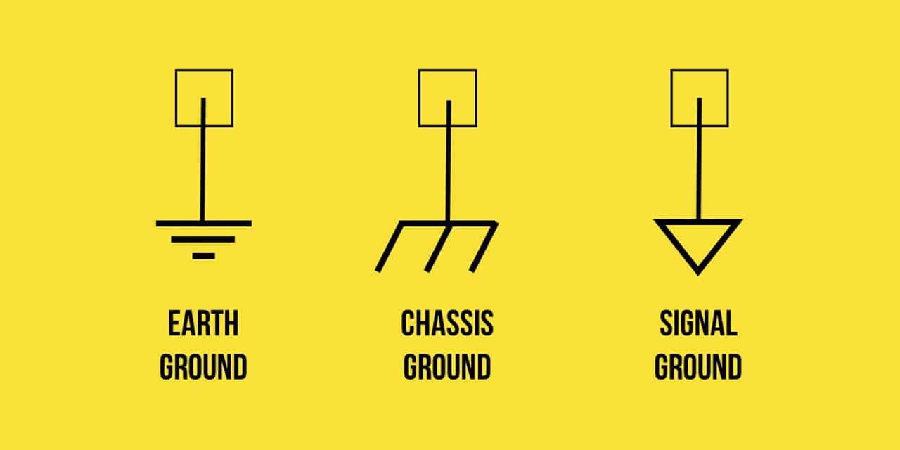
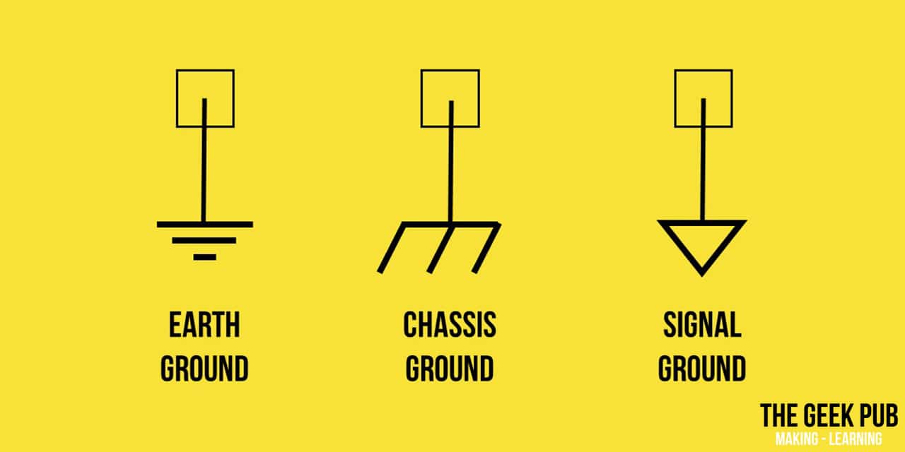
Let’s go through the types of grounds and learn more about them. The three most common you will find are Earth Ground, Chassis Ground, and Signal Ground. But we will also talk about a few others.
Earth Ground
This is the most common type of ground that ordinary people think of outside the electronics or automotive worlds. Earth ground means exactly what it sounds like. We’re connecting our system to the planet below us (aka. Earth). Most all structures, buildings, and homes have an earth ground. In fact, the ground pin on your electrical plugs and outlets eventually lead to this ground. A large metal rod or pipe is generally driven into the ground near the electrical panel on the outside of the structure and then connected to the ground bus on the same panel.
In addition to electrical systems, most radio towers and tall structures have a lighting rod which is also connected to earth ground and must be capable of carrying significant voltage and amperage loads to the ground and away from the sensitive electronic systems on the tower. Some of these systems even resort to the burring of large copper plates under the structure to distribute the lightning strike more effectively.
Chassis Ground
Connecting to earth ground is not always practical, or even possible. In applications such as automobiles, portable computers, and electronic devices there is no practical method of keeping the device connected to earth ground. I mean you don’t want to drag 200 mile long cord behind our car after all! In these applications In these applications, a ground plane is usually selected to be the common reference point for 0 volts. In cars, this usually the frame or largest metal structure of the vehicle in the case of a unibody. In electronic devices such as laptop computers, a rail on the mainboard usually becomes the ground location.
Signal Ground
In other applications, you may have many different voltages in a single application. An example of this is in a audio amplifier where there may be many different circuit boards, some may be running at 12v and 1 amp, while another board may have very high current at 5v for driving a speaker. Signal ground provides a way to ground these systems independently but allow them to still work together. This also prevents serious interference and buzzing sounds in the types of applications.
Floating Ground
In some systems, there is a power supply transformer in place. By its nature this transformer will isolate the ground of the electronics circuit from the mains circuit. Simply put, the power supply will have an earth ground, while the circuit on other side will have a chassis ground. This is very common electronic devices that plug in to charge, and then run off of battery when unplugged.
Virtual Ground
A virtual ground is when a node of a circuit is maintained at a steady reference potential, without actually being connected directly to the reference potential. This a very commonly found in operational amplifiers (Op Amps). Although a virtual ground always has a steady reference, it cannot and should never be used as an actual ground.
More About Different Types of Grounds
Now that you know about the different types of grounds, let’s talk about some other grounding fundamentals you might need to know as you do your electronics projects!
Ground Loops
Have you ever been in a large auditorium and someone plugs in a microphone and all you hear is a hum. A hum that sounds like it cycles at 50hz or 60hz? You probably were experiencing that hum from a ground loop!
A ground loop happens when two different electronic systems that have their own mains voltage and grounds are connected together over a section of wire. In these cases the reference point of 0 volts is not the same in both systems! They have different potentials, and therefore form a potential over the loop. This is the very reason that ground loop isolators exist!
Chassis Ground Isn’t Always Perfect
You may be inclined to think that with something like a chassis ground on your vehicle that your good to go and will never have an issue. Well, remember earlier when we said that it’s not always true? Some types of grounds are more likely to experience potential issues than others. Pun intended.
On large vehicles, such as cruise ships or airplanes, it is quite common to find that the potential varies slightly from deck to deck. As an airplane flies through the atmosphere it is not uncommon for the Earth’s magnetic field at 480+ mph for a small electric current to be introduced to the airframe! It will also be likely to vary depending on windspeed, altitude, and other variables that act on the plane.
Also remember, that a transformer is nothing but a winding of wires at the end of the day. Parallel traces on circuit boards, or excess looped wiring in your projects can become transformers under the right circumstances, creating a potential where none should exist!

