Most orders for IN STOCK items placed by 12PM CST M-F ship SAME DAY. Orders for custom items and prints may take additional time to process.
After my last video introducing the Arduino, some of you commented that you needed an example of how the Arduino works that is super simple to understand. So in this video we’re going to do the absolute simplest of projects. We’re going to be blinking an LED!
We’ve made detailed tutorial video on this topic that we think you might enjoy!
We will attach an LED to PIN 12 of the Arduino and make it blink on one second intervals. We’re not even going to use a breadboard in this project. We will only require an LED, a 220 Ohm resistor, and 6 lines of code. And the last of those 2 of those lines are just repeats with the LED state changed.
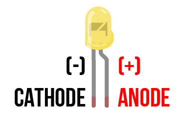
What is an LED? An LED is a light emitting diode. A diode is an electronic component that limits the flow of current to one direction. An LED is just a diode that emits light, but the same rules apply. This is why unlike normal light bulbs, an LED has a positive and negative lead (more accurately an anode(+) and cathode (-) lead).
You can tell which leg on the LED is which in two different ways. The first way is the cathode (-) side of the LED will have a flat notch on the plastic housing where it won’t be completely round. The second way to tell is that that the cathode (-) lead is always shorter than the anode (+) lead.

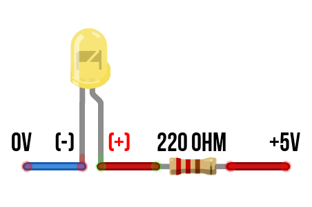
In order to limit the amount of current traveling across the LED and burning it out, you’ll need to add a resistor in line with it to protect it. In our case that will be a 220 ohm resistor. Failure to use a resistor will result in your LED failing, whether immediately or over a short period of time.

In many of the Arduino tutorials on the web they will show wiring this circuit without a resistor and attaching to PIN 13. They will claim pin 13 has an integrated resistor. This is true, but their assumption is wrong. The resistor is wired in parallel to pin 13 and only protects the integrated on-board LED. If you follow those tutorials you will ultimately burn out the LED or even worse fry the ATmega micro-controller. Don’t do this. Use a resistor!

If you’d like to do this project, we’ve created a simple parts list for you to get started:
| QTY | PART / LINK | ||
|---|---|---|---|
| 1X | Arduino Uno | ||
| 1X | USB Type B Cable | ||
| 1X | LED Kit | ||
| 1X | Resistor Kit (220 Ohm) | ||
| 1X | Solderless Breadboard | ||
| 1X | Jumper Wires |

In order to make this project for blinking an LED as simple as possible to understand, we’re going to skip the breadboard completely. The first thing we’re going to do is just wrap one leg of the resistor around the anode (or positive) lead of the LED. The anode is the longer lead.
Now that we’ve done that, we will insert the cathode (or negative) lead of the LED into the Arduino ground pin. The cathode is the shorter lead.
Now, take the other lead of the resistor and plug it into PIN 12. You can actually use any of the digital I/O pins on the Arduino for this, and after this video you should experiment with moving it around and just changing the pin number in the code!
That’s literally all there is to the hardware side of this project.
RELATED: List of Arduino Sensors
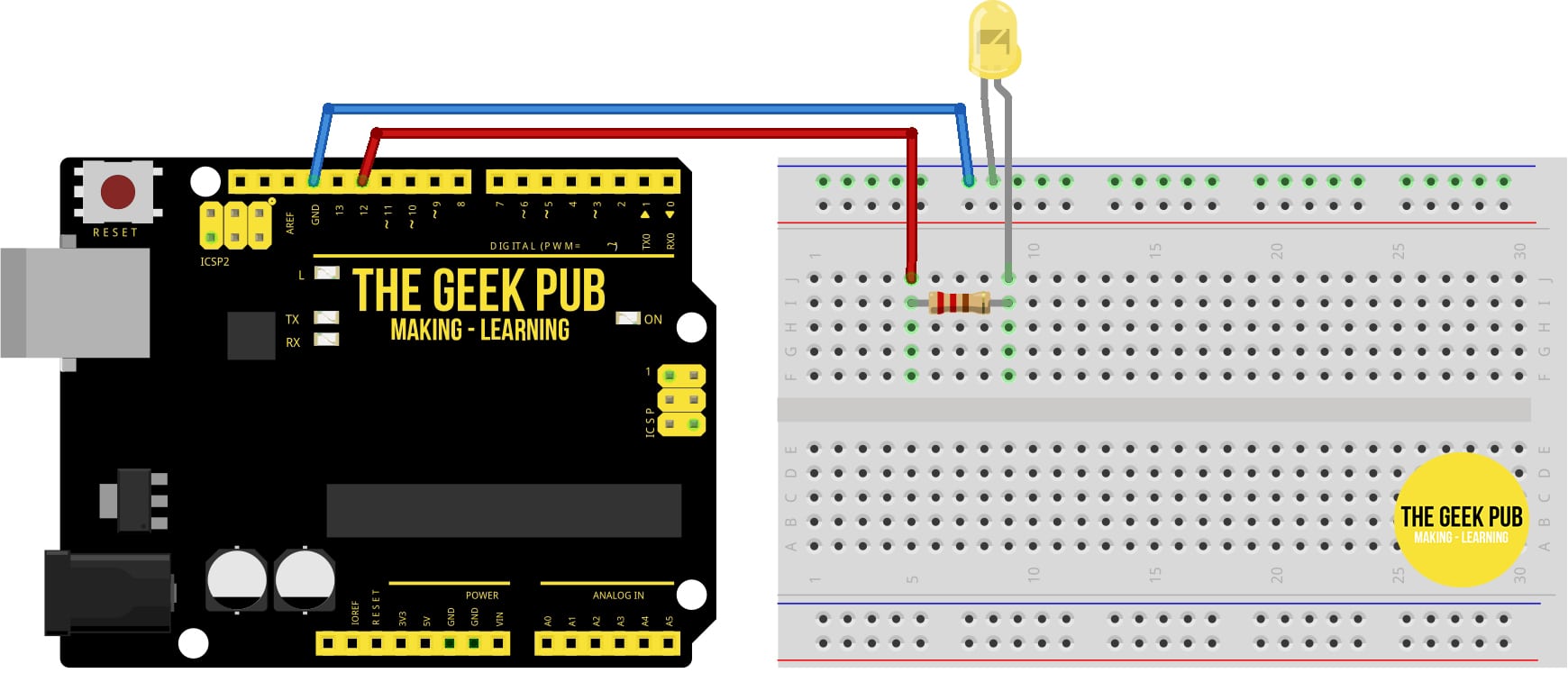
If you’d like to use a breadboard to wire the LED, its just a little bit more complicated (barely). Here’s how to do it.

Now lets move over to the software side. Open the Arduino IDE. You’ll see a void setup, and a void loop. These are the two main functions of the code for blinking an LED on the Arduino. The setup function is where you configure things. The loop function is just what it sounds like. All code you put here will just execute over and over again for infinity (or until the Arduino loses power).
Above the setup function let’s add one single line of code:
int LED_PIN = 12;
This just defines an integer variable and makes our code easier to understand. In our setup function, we need to add another single line:
pinMode(LED_PIN, OUTPUT);
This tells the Atmega that we’re going to use PIN 12 to output 5V. In the loop section we’ll add four more lines to turn the LED on and wait one second and then turn it off:
digitalWrite(LED_PIN, HIGH);
delay(1000);

digitalWrite(LED_PIN, LOW);
delay(1000);
And put it all together you get the following completed Arduino LED blink code:
/*
    ARDUINO BLINK AN LED TUTORIAL
    By: TheGeekPub.com
    More Arduino Tutorials: https://www.thegeekpub.com/arduino-tutorials/
*/

int LED_PIN = 12;

void setup() {
  pinMode(LED_PIN, OUTPUT);
}

void loop() {
  digitalWrite(LED_PIN, HIGH);
  delay(1000);
  digitalWrite(LED_PIN, LOW);
  delay(1000);
}
Now save your code using file, save and give it a name. I chose BlinkLED.ino.
To program your Arduino for blinking an LED, just click the arrow button at the top left corner and your code will compile and upload to the ATmega micro-controller. Within a second or two your LED should start blinking.
That’s the power of the Arduino platform. It’s incredible simple and easy to understand.
As you’ll learn in future tutorials, the delay() function stops all running code on the Arduino until it has completed its delay. This is not optimal for many programs. For example, you might miss a button press if the Arduinio is executing the delay() function when you press it! The following code will allow you to blink the LED without using the delay() function for the times that need it.
// constants won't change. Used here to set a pin number:
const int LED_PIN =  12; // the number of the LED pin

// Variables will change:
int ledState = LOW;             // ledState used to set the LED

unsigned long previousMillis = 0;        // will store last time LED was updated

// constants won't change:
const long interval = 1000;           // interval at which to blink (milliseconds)

void setup() {
  // set the digital pin as output:
  pinMode(LED_PIN, OUTPUT);
}

void loop() {
  // Put code that needs to be running all the time.

  // check to see if it's time to blink the LED;
  unsigned long currentMillis = millis();

  if (currentMillis - previousMillis >= interval) {
    // save the last time you blinked the LED
    previousMillis = currentMillis;

    // if the LED is off turn it on and vice-versa:
    if (ledState == LOW) {
      ledState = HIGH;
    } else {
      ledState = LOW;
    }

    // set the LED with the ledState of the variable:
    digitalWrite(LED_PIN, ledState);
  }
}
If you want to take this to the next level, you’ll just need six LEDs and and six 220 Ohm resistors. Connect the resistors and LEDs to pins 7 through 12 and upload the following code to your Arduino. If you’d like more information on this and would like multiple examples, check out our Arduino Knight Rider and Cylon Eye article.
int pinArray[] = {12, 11, 10, 9, 8, 7};
int count = 0;
int timer = 10;

void setup(){
  for (count=0;count<6;count++) {
    pinMode(pinArray[count], OUTPUT);
  }
}

void loop() {
  for (count=0;count<5;count++) { digitalWrite(pinArray[count], HIGH); delay(timer); digitalWrite(pinArray[count + 1], HIGH); delay(timer); digitalWrite(pinArray[count], LOW); delay(timer*2); } for (count=5;count>0;count--) {
   digitalWrite(pinArray[count], HIGH);
   delay(timer);
   digitalWrite(pinArray[count - 1], HIGH);
   delay(timer);
   digitalWrite(pinArray[count], LOW);
   delay(timer*2);
  }
}
You’ll get this awesome Knight Rider effect on your LEDs!
If you run into any problems with this project, leave a comment below and we will do our best to help you out!
Now you can go on to the next tutorial, back a tutorial, or back to the index!
If you like our content maybe consider upgrading to Premium. You’ll get access to
3 Responses
5
I loved it when you ramped it up! How awesome was that. Knight Rider was my favorite show as a kid.
5